There are a lot of great aeration kits that take the guesswork out of calculating the individual components associated with properly aerating your pond. Most of these kits are designed by parameters of pond depth and pond volume. And for many pond owners, this works great.
You may have a specialized application and you don't want or need an entire kit. Whatever the reason, understanding and calculating the backpressure &/or friction loss of each component of your system can help you to save time and money. Your pond and fish will thrive too.
To properly find the air pump that is right for your pond, you will need to calculate your system backpressure. Follow these steps. Feel free to use our calculators that are associated with each of the steps. Please be aware that the calculators are sometimes slow to load because they are embedded from software outside of our website.
Calculating Your System Backpressure: Units of measure PSI
1. Calculate Water Depth Backpressure: Pond Depth - every 2.31’ of depth adds 1 PSI of pressure. Divide your pond depth by 2.31 to find your water depth backpressure.
Example: Your pond is 4' deep. Divide 4' by 1.73' = 4'/2.31' = 1.73 PSI. The water pressure for a 4' deep pond is 1.73 PSI.
Use the calculator below by entering your pond depth in feet to get your backpressure. Hit your enter key after entering your pond depth to get your answer.
2. Calculate Diffuser Backpressure: Diffusers may be labeled as fine, medium, or coarse diffusers. Typically, the outliers of fine and course diffusers are for specialized applications. Medium works best for most applications and Matala® offers great diffusers that are labeled as fine diffusers and they state that they have the lowest back pressure membrane diffuser rates on the market. Matala® states their diffusers offer less than 6" of backpressure. Be sure to enter the diffuser backpressure depth in feet. In this case, 0.5 would be entered since 6 inches equals 1/2 of a foot.
Use the calculator below by entering your pond depth in feet to get your backpressure. Hit Enter after entering your diffuser backpressure.
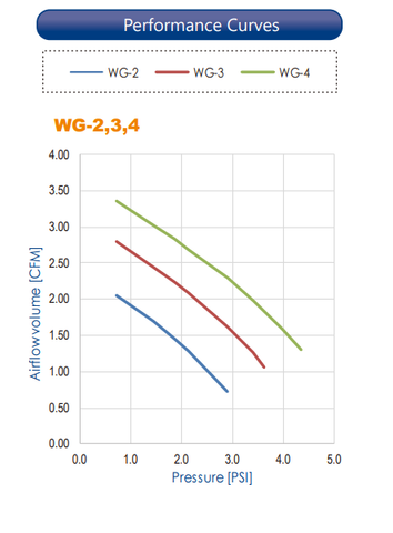
3. Evaluate the Your Desired Compressor - Your desired compressor will have a Volume/Pressure graph. It may be called a spec sheet, performance graph, etc. Here's an example of 3 different Hiblow compressors on 1 graph. Each colored line represents a different compressor and that compressor's working range. The X-axis represents pressure in pounds per square inch (PSI). The Y-axis represents the air volume in cubic feet per minute (CFM). As you can see from the graph, there is an inverse relationship between pressure and air volume. The more pressure exerted on the air pump, the less volume of air the compressor can produce and vice versa. This is why it is important to size your air pump accordingly, as this will save the life of your air pump, as well as aerate your pond properly.
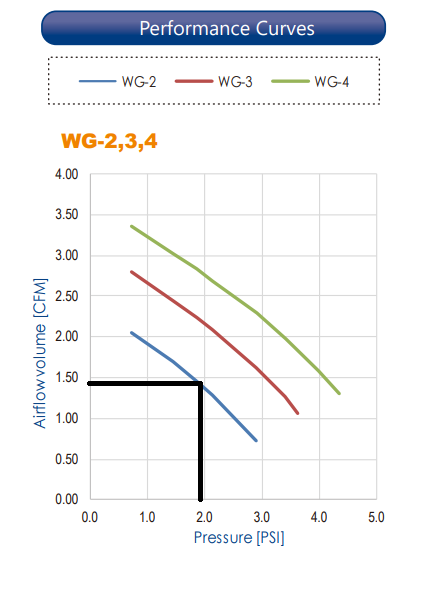
Next: Add your backpressure found in Step 1 and Step 2 together. This backpressure that you found in previous steps 1 & 2 (1.73+ 0.22 = 1.95 PSI) will be the number on the x-axis. Find the 1.95 location on the X-axis and slide up the graph to where the line intersects the WG-2 pump curve. Slide across to where this intersects the Y-axis and this will be the air flow (CFM) at that pressure. See the black line on the graph below. This compressor will have approximately 1.4 CFM of airflow at 1.95 PSI.
4. Calculate Airline Friction Loss (Distance of airline from compressor) - How far will the airline need to be from the compressor.
A few things to keep in mind: Weighted airline won’t float so you will need to account for the depth of the airline. 3/8” ID weighted tubing is a common size for water gardens but typically for lengths shorter than 50’.
Rule of thumb: 3/8” ID tubing up to 50 feet - longer lengths beyond 50' create more friction loss (added backpressure) and less air flow too, ½” ID tubing from 50’-100’, and ¾” tubing longer than that.
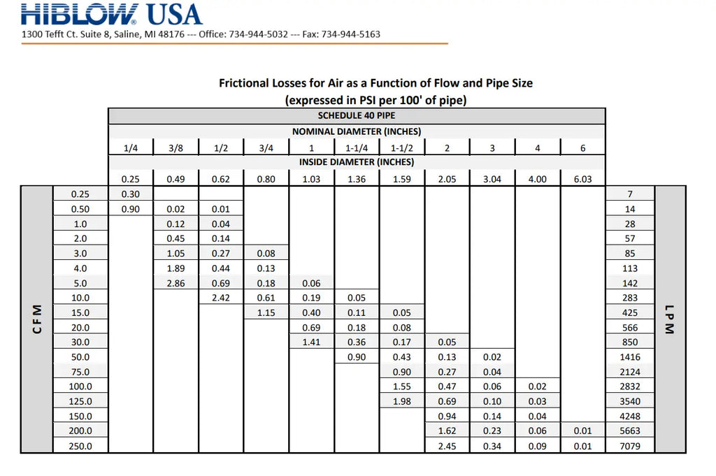
The chart below references frictional loss in PSI in 100' of tubing. Add you backpressure found in Step 1 and Step 2 together. This backpressure that you found in previous steps 1 & 2 will be the number in the row (left side for PSI). From there, we can evaluate our tubing based on the diameter column (top) to see the frictional losses.
Example: We need 50' of airline and our backpressure from Steps 1 & 2 is 1.95 PSI. A 3/8" x 100' length tubing with a 1.95 CFM (we rounded up to 2.0 CFM) has a backpressure of 0.45 PSI. From the 3/8" column, slide down until you reach the 2.0 CFM row (left side). Keep in mind that the backpressure of 0.45 PSI is for 100' of tubing. If you are using only 50' of tubing, you can divide that in half. Your backpressure for a 50' section of 3/8" tubing at 2.0 CFM would be 0.225 PSI. For this example, we will stay with the 3/8" diameter tubing but would move up to the 1/2" diameter if we needed the 100' of tubing.
5. Calculate Total System Pressure: Water Depth Backpressure (Step 1) + Diffuser Backpressure (Step 2) + Airline Friction Loss (Step 4)
For our example, our total system pressure using 3.8" diameter tubing is 1.73 PSI (Step 1) + 0.22 PSI (Step 2) + 0.225 PSI (Step 4) = 2.175 PSI. Now would be an ideal time to verify that our airflow is within the diffuser manufacturer's specs.
The Matala® spec sheet shows the BHB-MD225 model has a recommended air flow of 0.9-4.2 CFM. Based on our value figured in Step 5 of 2.175 PSI, we can check our air pump graph, using 2.175 PSI on the X-axis and going up until we intersect the WG-2 pump and slide across until we intersect the Y-axis. That value is approximately 1.3 CFM. We will get 1.3 CFM of air flow from the WG-2 air pump with a pressure of 2.175 PSI.
To Summarize:
Enter pond depth in feet in Step 1
Enter Diffuser Depth Backpressure in Step 2
Find your air pump based on the system-generated number in the bottom calculator.
Add Airline Frictional Loss Value
Your Total System Pressure will be calculated.